Engineer’s Log, Labdate 0712.21. Due to a severe galactic cosmic ray storm we were completely cut off from the Earth. Uhura picked up a weak radio signal from RC command today and we are confident that communication will be in normal state within hours.
I came up with some interesting ideas for the graphic extension project while digging into the details of the CBM video system, but: Too many ideas, too little time! So I’ll have to keep my hands off the more sophisticated topics for now and focus on a quite simple approach.
Ok, so what’s the final plan for this Retrochallenge?
- Name the thing to improve blog readability. I’ll call it High Resolution Extension and use the abbreviation HRE from now on. (done!)
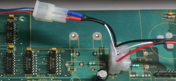
- Construct a minimally invasive hardware. Avoid soldering at the CBM mainboard if possible. Use connectors instead.
- Consider it a success if a resolution of 320 x 250 can be accomplished but aim at a resolution of 640 x 250.
- Combine the CBM video signal and the HRE video signal so that the following modes can be used:
– CBM text mode without any HiRes graphic (default)
– HRE graphic mode without any CBM text
– CBM text and HRE graphics combined - Control HRE through the User Port (POKE).
- Integrate some kind of processing unit for simple drawing tasks (aka GPU) to unload the main processor.
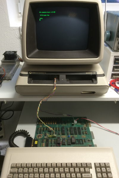
Fortunately there is a connector between mainboard and monitor and all video signals are connected to the user port, so the HRE will get all input signals from the user port and output signals to the monitor connector. An external supply will deal with the power input.
It seems as if we start off on the right foot. Can we fulfill part two of our plan so easily? Maybe, but we’ll have to consider timing issues. The CBM pixel clock is 16 MHz. In other words, a single pixel is a 62.5 nanosecond flash. A side by side display of HRE and CBM pixels requires a very precise syncronisation of the two pixels streams. To be cycle exact we should use the exact same cycles. – Easy! Let’s connect to the mainboard’s clock pulse!
Beware! Besides the fact that there is no connector to the main clock (and soldering violates part two of the plan) it would be an open-heart surgery. The main clock controls every function of the computer and if our circuit introduces any kind of noise to the clock system, we might end up with an unreliable device. Therefore I dropped this option. I’ll go with a separate clock and synchronize to the horizontal sync pulse.
Hardware Overview
The GPU will be an 8-bit microcontroller clocked at 16 MHz. I want to keep some memory up my sleeve, so a 128k x 8 bit SRAM will join the microcontroller. Add a latch, a shift register, multiplexers and NAND gates and you’ll get the HRE. Hopefully.
 Sorry. No complete schematic. And no PCB layout. Why not? Summer! We had beautiful weather here and I wanted to spend my spare time outdoors. Although I really enjoy PCB design, it’s a pain in the neck if you try it on a notebook in bright sunlight. Therefore a sketch on paper seemed appropriate and adequate. Doesn’t a real retro project need some retro design methods anyway?
The SRAM interface consists of
- AD7:0 multiplexed low order address and data bus
- A16:8 high order address bus
- ALE address latch enable
- /RD read strobe
- /WR write strobe
A16 is used for bank switching given that the microcontroller (ATmega162) can’t address more than 64k of external RAM. The data bus is linked to a parallel in – serial out shift register (74HCT597) that converts the data byte into a serial stream of pixel bits. Shift register and microcontroller are clocked by a 16 MHz crystal oscillator. IC 74HC257 works as a digital switch. It connects either the CBM video stream or a pullup resistor to the NAND gates (74AC00) where CBM pixel bits and HRE pixel bits are combined to a single stream (see truth table). The user port is linked to a free port on the microcontroller.
The circuit will be soldered on a stripboard and has been almost finished. Stay tuned!