A month has past since the end of Retrochallenge 2015/07 and … I miss the feeling! Yep, I miss the Retrochallenge feeling. That is, working on a challenging project just for fun. Specifically working on interesting stuff for ancient computers. Ok, I assume you’re one of the 0.0236986301 ppm of world population who do understand what I’m talking about if you’re reading this at all.
Therefore I won’t wait for RC 2016/01. I’ll continue to work on my RC 2015/07 project and turn the proof of concept into a working prototype. To be honest I already restarted the project and didn’t tell you. 😉
Finding the Vsync bug that showed up in the demo video (RC 2015/7 final post) has been the first task. As I have mentioned before it is critical to count every single cycle within the video output routines. And what happens when you work after work ’til late night? You sometimes can’t count anymore! The error was caused by a not equally timed program path. There is a reason why they call an oscilloscope “electronic engineer’s best friend”. Would have been clever to verify the counted cycles with my friend somewhat earlier…
Optimizing the code gave me some additional free cycles so I could increase the resolution from 640 by 250 to 648 by 256. It’s nothing to write home about but the extended resolution allows to draw small symbols outside the CBM text region which might come in handy in certain cases.
One page consumes 648 * 256 / 8 = 20,736 bytes of external SRAM. The size of the installed SRAM is 131,072 bytes (128k * 8 bit). How do we make use of the remaining memory? Several framebuffers! The ATmega162 can address 64k of external SRAM minus 1k internal SRAM minus 256 bytes registers. These 64,256 bytes contain 3 framebuffers and leave 2k for future ideas. The other half of the SRAM chip can be reached by banking. That equals to six independend framebuffers and two 2k free memory blocks in total.
The framebuffers can be used in two modes. In mode 0 all six buffers are orthogonal. In mode 1 only the three buffers in bank 0 are available for drawing while the three buffers in bank 1 are used to implement a second ‘color’. You may call this lower level of brightness ‘dark green’ as well as ‘transparent green’. The following image shows the extended resolution by a border drawn outside the CBM display real estate and explains the meaning of ‘dark/transparent green’.
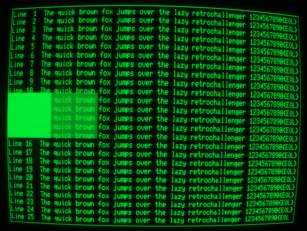 Please take a closer look at the characters ‘T’ in the bottom half of the screen and ‘1’ in ‘Line 21’ as well as the disruption of the right border line. These seem to be side effects of the wild wiring – sometimes present, sometimes absent. EDIT: No, it’s a problem of the CBM mainboard that persists even if I disconnect the HRE completely. Talking about the characters only. The line disruption is most likely a problem of the HRE. And no, it’s not the dust on my camera.
To get the second ‘color’ two associated framebuffers at the same address on different memory banks are used. The video output routine switches between these two buffers at a frequency of 25 Hz. If a pixel at a specific location is set in both framebuffers it will be displayed at full brightness. If it is set in one framebuffer only it will be displayed at half brightness. Due to the fact that CBM text is always displayed at full brightness it will shine through in areas of ‘dark green’.
Unfortunately the applicability of this second ‘color’ is very limited: A refresh rate of 25 Hz implies severe flickering. Adjusting the potentiometer at the back of the screen to reduce overall brightness might help a bit but won’t provide a good display quality.
I plan to modify the user port communication but haven’t come up with a better solution. A first attempt to implement a more sophisticated protocol killed the balanced timing.