Engineer’s Log, Labdate 0719.21. Mr. Spock remarks that our computer underperforms even the human brain. That’s nice to hear.
I already had a look at LunaAVR about a year ago but haven’t used it for a real project until now. That’s simply because I haven’t worked on a private microcontroller project last year. LunaAVR has a nice IDE and comes with more than 300 pages of documentation as well as many example programs. There seems to be a small but informed and responsive community. After all it might be the right tool for the job.
Last night I tinkered a bit with the new release. It still lacks support for the external memory interface that I want to use. No big deal, though. Flipping some bits should turn XMEM on (it’s an Atmel term for eXternal MEMory) and memory access will be handled by assembler anyway.
Where do we start? The CBM 8296 should behave as usual until a special command is issued to activate the HRE. For that purpose we have to set pin 9 of the shift register (output) to high level and pin 1 of the multiplexer (A/B switch) to low level so that only the CBM video signal is routed to the monitor. A 10k pulldown resistor takes care of the multiplexer but the shift register has no tri-state output and therefore the microcontroller must initialize the chip. While we’re at it: a subroutine for switching three video modes (CBM only / HRE only / both) would be nice.
Video synchronisation will be next.
IF you haven’t tinkered with video signals
THEN you might find the following (greatly simplified) abstract of avail
ELSE skip next four paragraphs
The CBM has a CRT (Cathode Ray Tube) monitor that sends an electron beam onto a fluorescent screen. The electron beam moves continually across the screen area in a fixed pattern starting at the upper left corner. It then moves horizontally to the right screen border, then back to the left border and down by the width of a pixel. This movement repeats until the beam reaches the bottom right corner of the screen. It then moves back to the upper left corner and the whole process starts again. In other words, the beam moves from left to right and line by line from top to bottom – just like you move your eyes while reading this text.
Three digital signals control the beam. In this text they are labeled VIDEO, HSYNC and VSYNC. One can’t see the beam as long as VIDEO is HIGH. If VIDEO is LOW then the fluorescent coating lights up at the current position of the beam. If HSYNC (Horizontal SYNChronisation) is HIGH the beam passes from left to right along the screen. If HSYNC is LOW the beam moves one line down and back to the left. HSYNC is like Carriage Return and Line Feed for the beam. While VSYNC (Vertical SYNChronisation) is HIGH the beam moves down the screen line by line. The beam returns to its home position (upper left corner) when VSYNC is LOW.
How do we display useful information? By precisely controlling the LOW periods of VIDEO. A long LOW period gives a long horizontal line and a short LOW period gives a short line. Our horizontal timing reference is the 16 MHz pixel clock of the CBM system. 16 Mhz pixel clock means that a single pixel has a duration of 1 / 16,000,000 s = 62.5 ns. Let’s assume we want to display a horizontal line of 8 pixels width. We then need to drive VIDEO LOW for 8 * 62.5 ns = 500 ns. A complete set of pixel information that can be displayed on the screen at a time is called a frame. The vertical timing reference is called frame rate (or refresh rate). It tells us how many frames per second will be displayed, that is how many VSYNC pulses occur per second. My CBM system uses a frame rate of 50 Hz.
Back in the days most computer monitors had quite simple (aka cheap) circuits inside. This tended to result in performance variations within a production lot and in temperature dependency of the display. Imagine they would have used the whole screen area to draw pixels and the start position of the beam moves slightly to the left while the monitor heats up. Some pixels would disapear behind the chassis of the screen. Thus borders were introduced to the timings.
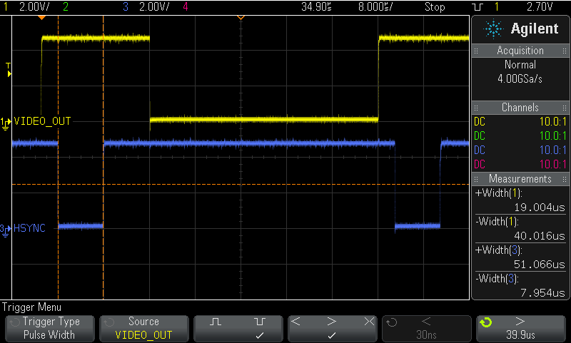 This oscillogram shows a line of 640 bright pixels between two HSYNC pulses. The LOW period is 40 µs which is just what we expect (40 µs = 40,000 ns; 40,000 ns / 640 = 62.5 ns; 1/62.5 ns = 16 MHz). The HIGH period of 19 µs forms the horizontal borders. It takes about 16 µs from HSYNC going LOW to VIDEO_OUT going LOW and about 2.9 µs from VIDEO_OUT going HIGH to HSYNC going LOW. These periods define the horizontal position of the visible area.
To synchronize the HRE output with the CBM output I’ll use an interrupt that is triggered by HSYNC. Due to the fact that we have to be cycle exact in our timing we must take interrupt latency into account. The ATmega completes any ongoing instruction before an interrupt can be serviced. Since execution times vary from 1 to 4 cycles per instruction, an interrupt service routine has a random entry time. The solution to this problem is to put the µC into sleep mode. It then always executes the exact same steps when it wakes up and these will take always the exact same time to execute.