Engineer’s Log, Labdate 0725.22. Science Officer Spock finally managed to persuade the computer to accept the modification. We are traveling at warp 4.4 now. Warp 5 should be possible, though.
Ok, I swapped pins PE0 and PD0 to free an interrupt for VSYNC detection and added the interrupt service routine. Luckily vertical synchronisation worked right from the start. 🙂
Sadly, tracking down the jitter problem isn’t that easy. At first glance it appeared to be a small difference in frequencies (main clock CBM vs. main clock HRE) so I tried to run the HRE on the CBM’s main clock and it improved somewhat. The jitter disappeared for one or two minutes to be precise – then returned. Cooling spray helped to locate the source of the problem: It’s the hex inverter chip (UD3) that forms the oscillator circuit. Really? I carefully examined the CBM text on the screen and there wasn’t any jitter at all. Only the HRE output showed jitter. Then I touched UD3 with my fingers and the jitter changed or disappeared. Unfortunately I have no spare finger to add to the circuit…
My provisional conclusion: The jitter is caused by the marvellous wiring and perfect grounding/shielding of the HRE board <ahem>. As we are pinched for time I won’t design a proper PCB to solve this problem. Rearranging the cabling helps a bit…
A screen full of equally spaced vertical lines is of avail when checking horizontal sync but otherwise quite boring. A screen full of freaking awesome vertical lines would require variable spacing! Easy! Just change the bit pattern and … fail.
For the first test I wrote a bit pattern to the external SRAM and imported the data in the next cycle to the shift register then clocked the bits out of the shift register to the monitor.
LDI r25, 0b01111110 // load register 25 with bit pattern
ST $8000, r25 // store register 25 value into SRAM
OUT CtrlPort, r19 // load data into shift register
OUT CtrlPort, r20 // start clocking bits out of shift register
NOP // waste one cycle
NOP // waste one cycle
These six instructions take 8 cycles which is the time that is needed to clock 8 bits (pixel) out of the shift register. In other words 8 pixels are loaded and sent out to the monitor in 8 cycles thus allowing for a pixel frequency of 16 MHz.
Along with changing bit patterns for variable line spacing I coded a complete framebuffer handling as it will be needed for a graphic extension. Now I was reading the bit patterns from SRAM and then transferring them to the shift register. It turns out that the byte that has just been read from SRAM stays valid on the data bus for only one clock cycle (when /RD is LOW). The following OUT instruction cannot see this data anymore thus the transferred byte is not correct.
First idea was to send the data (that has been read into a microcontroller register) out to another port and import into shift register from that port. That would work if we had a free port.
Second idea was to handle the external SRAM manually but that would take much more clock cycles and reduce the horizontal resolution.
Third time is a charm: Enable XMEM, read bit pattern from external SRAM, disable XMEM, enable manual output on port A, send bit pattern to port A, import into shift register, start shifting. That results in 9 clock cycles which is still one cycle too many <Ҥ$+#%&/()!!!!> Fortunately the XMEM interface overrides any conflicting port definition if enabled and restores the old definition if disabled. So I could remove the port definition from the framebuffer read sequence and saved a cycle.
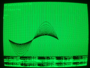
Meanwhile I wasn’t positive about vertical lines at all and programmed a bunch of sinewaves instead:
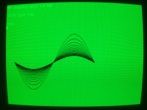
After some time of debugging the sinewaves appeared in a more pleasant fashion:
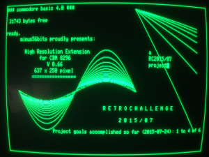
Men are like little kids so I played with my new toy: Border, lines and sinewaves have been computed by the HRE microcontroller. Text has been typed on the CBM keyboard. Due to the fact that the HRE has a separate video memory one can type and edit text/programs as usual without destroying the graphics. Current resolution is 637 x 250 pixels. Hopefully an additional debugging session will find the lost three pixels per line.
Implementation of the userport interface will be next. Stay tuned!