It’s a matter of common knowledge that a breadboard isn’t suitable for high frequency circuits. But 0.025175 GHz is almost DC, right? Not at all! In particular, one will find fast edges, even in most digital circuits that are clocked really slow. It’s not only the system clock we have to worry about when prototyping on a breadboard. These fast edges may contain high frequency components up to several hundred MHz.
Nevertheless I’ll start on a breadboard. Why? To test a few things before going any further. Okay, maybe there is also a tiny bit of curiosity involved. 😉
But before we go to the breadboard we need to do some math. Please stay with me! It’s basic arithmetics only. Promise!
The PET displays 40 x 25 characters using an 8 x 8 pixel monospaced font. The corresponding screen resolution is
40 * 8 = 320 pixels horizontal,
25 * 8 = 200 pixels vertical.
Having this resolution for color graphics would be great, as we could print text in the original PET font side by side to color graphis at the exact same pixel size.
As mentioned before a horizontal resolution of 640 pixels equals to a Dot Clock of about 25 MHz in the VGA universe. For a resolution of 320 pixels the Dot Clock is halved, too (25 Mhz / 2 = 12.5 MHz). The plan is to store the color of a pixel in a single byte, so 2 * 2 * 2 * 2 * 2 * 2 * 2 * 2 = 256 colors are possible (Sorry, but I had to keep a promise. For really advanced mathematicians out there that is 2^8). Thus the circuit will have to spit out a byte per pixel – that is 12.5 megabytes per second!
All video data resides in external RAM. Transfering a byte (pixel) from external RAM to the DAC (Digital Analog Converter that converts pixel data into VGA compatible voltages) requires four steps:
Precondition: RAM is in read mode
1) calculate RAM address
2) feed address to RAM
3) read color byte from RAM
4) send color byte to DAC
Assuming that each of these steps takes a single clock cycle, a system clock of 4 * 12.5 MHz = 50 MHz is needed. The ATmega1284 is rated for a maximum clock frequency of 20 MHz. Oops.
Fortunately two of these steps are unnecessary. We can avoid steps 3 and 4 by connecting the external RAM data bus straight to the DAC. The microcontroller will act merely as a counter then. Wouldn’t it be easier and cheaper to perform this task with a standard resettable counter chip? Well, it’s possible for sure (PET 2001 video circuit consists of 74xxx logic only), but in my view it’s more convenient and flexible to substitute a microcontroller for a bunch of logic chips here. Anyway, in both cases we end up with dealing with two logical steps. The question is if the above assumption is true: How many clock cycles does the ATmega really take to perform these steps? Ooookay, the party is over! We’re talking assembler and count cycles from now on…
Come on! Stop crying! Real programmers do talk assembler and do count clock cycles. End of story.
The ATmega1284 datasheet (in fact it’s more of a databook), chapter 29, Instruction Set Summary, is our friend: It takes one cycle to increment or decrement a register and it takes one cycle to output a register value to an I/O port. Therefore a pixel can be addressed in two clock cycles. That’s great news! Assumption verified! We need a system clock of only 2 * 12.5 MHz = 25 MHz. …
Only? That’s still 5 MHz more than the 20 MHz the ATmega is specified for.
Guess what? First task on the breadboard will be pushing the ATmega1284 to its speed limits. I’ve done overclocking on other AVR chips before. A stable external oscillator is key to maximum speed. The test circuit is pretty simple:
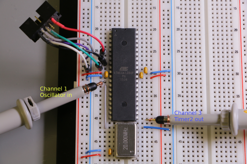 Just the controller, an external crystal oscillator, a bunch of capacitors, a programming header and two oscilloscope probes. All tests will be done at 5 volts. We start at 20 MHz to make sure everything is working correctly when the clock is within specification.
The program is quite simple as well. It’s the setup of Timer2 to toggle PD7 on compare match and an endless loop doing nothing: 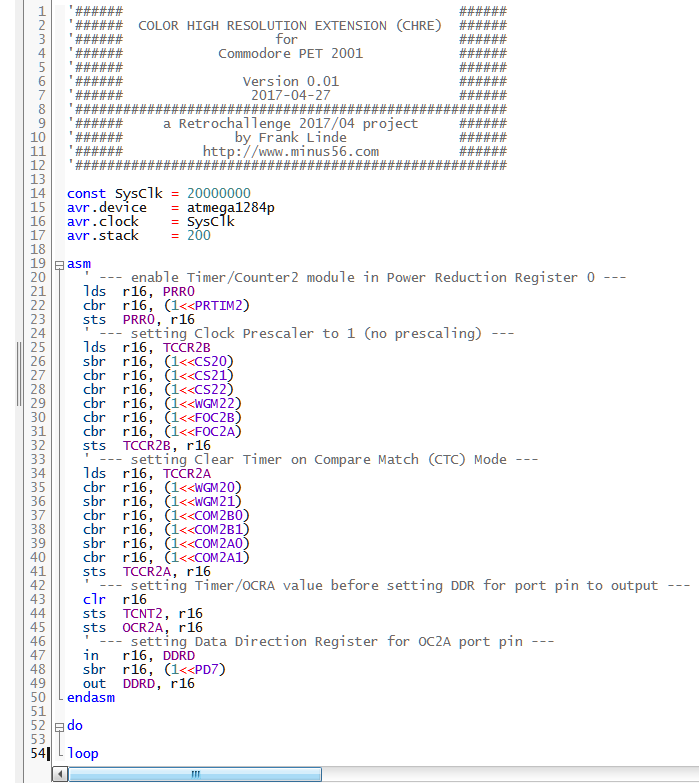
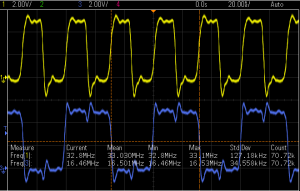
According to the datasheet this configuration is specified for a maximum toggle frequency of SysClk / 2. A quick look at the scope verifies that the frequency at PD7 is about 10 MHz. So far so good.
Now we’ll raise the frequency until the circuit stops working correctly. My junk box offers 25, 28.322, 32, 33, 36, 40, 48 and 50 MHz…
Tataaa!!! Aaand the winner is:
 33 MHz!!!

Wow! That will give us a reasonable safety margin when running at 25 MHz!
Only three days left and counting…