Originally I wanted to put all machine language routines into an EPROM at one of the ROM expansion sockets, but in contrast to the PET 8000 series the PET 2001 has no ROM expansion sockets. Fortunately, it has 6540 ROMs which cannot be substituted by ‘modern’ 27xx EPROMs. ‘Fortunately’??? Yes, because this prevents me from patching the Kernal and/or BASIC ROMs. 😉
Next resort are the cassette tape I/O buffers. Last winter I bought a SD card mass storage device for the PET series, called petSD+ (designed by Nils Eilers). It connects to the IEEE 488 port and pretends to be a floppy drive, so I don’t depend on a tape drive anymore. Off topic: Honor to whom honor is due. I bought my petSD+ from Dave Stevenson, who is one of the most kind and cooperative guys I’ve met on the internet. Thanks again for your great support, Dave! 🙂
The PET series supports two tape drives, each of which has an associated RAM buffer of 192 bytes (tape I/O buffer #1 $027A – $0339; tape I/O buffer $033A – $03F9). Just for the record: Without intending to appear ungrateful I would like to point out that 384 bytes really isn’t a giant amount of RAM, thus I’ll start with a basic version of the API and maybe add convenience later – at the expense of BASIC RAM.
This is my preliminary solution: Three integer variables are reserved for parameter passing. These variables must be assigned before any other variables are used in the BASIC program and they have to be assigned in a specific order! The ML subroutine expects to find the parameters in the order ‘drawing instruction’ [0..63], ‘parameter #1 [0..639]’, ‘parameter #2 [0..479]’ at the start of the variables in memory. Example:
0 REM ### CHRE SETUP ###
1 REM ### DO NOT MODIFY ! ###
2 DI%=0 : P1%=0 : P2%=0
3 REM ### END OF CHRE SETUP ###
The subroutine doesn’t care about variable naming, so someone might use this
2 Z6%=0 : BT%=0 : A%=0
Warning! Doing this may have serious side effects such as long-lasting headaches!
To command the CHRE we need to assign appropriate values to the variables, then call the subroutine. The following example positions the graphic cursor at X=321, Y=290:
1000 DI%=3 : P1%=321 : P2%=290 : SYS 635
Granted, that’s not as elegant as
1000 GCURSOR (321, 290)
but it does the job.
A BASIC integer variable is stored in 7 bytes. Bytes #0 and #1 contain the name and type of the variable, byte #2 the MSB and byte #3 the LSB of the 16 bit value. Bytes #4 to #6 are not used. Yep, Billysoft looks back on a long tradition of wasting RAM. BASIC stores a pointer to the start of the variables at address 42/43 ($2A/$2B). Please note that variables are stored in sequence MSB/LSB and pointers are stored in sequence LSB/MSB. Yep, Billysoft looks back on a long tradition of confusing people, too.
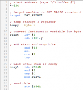
Let’s take a look at the source code:
Lines 11-12: The subroutine’s entry point is labeled ‘start’ (address 635 / $027B). Indirect indexed addressing is used to fetch the LSB of the first variable (aka drawing instruction).
LSB
ddddddd
Lines 15-18: We mask bits #6 and #7, shift left by 1 and add 1 (aka add start and stop bit):
LSB 63 RESULT
xxdddddd AND 00111111 => 00dddddd
LSB RESULT
00dddddd ASL => 0dddddd0
LSB 1 RESULT
0dddddd0 ORA 00000001 => 0dddddd1
Backup result in register Y.
Lines 21-24: Serial communication is a low priority task on the CHRE side, so we have to check if CHRE is ready to receive before we start the transmission.
Line 27: Data is transfered to the shift register. Shift out starts immediately.
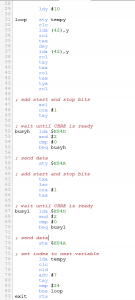
Line 29: We ignore the MSB just to show Goliath that David can waste even more RAM and set the index to LSB of the second variable (aka parameter #1).
Lines 31-34: Now we have to deal with values up to 639, thus we need to convert into two 6 bit values. Accumulator, register Y and register X will be used, so we backup the index value first. Then we clear the carry flag, as we are going to rotate through carry. Indirect indexed addressing is used to fetch the LSB of the second variable (aka parameter #1). Rotate left through carry:
C LSB C RESULT
0 dddddddd ROL => d ddddddd0
Lines 35-38: Backup result in register X. Set index to MSB. Fetch MSB of the second variable (aka parameter #1). Rotate left through carry:
C MSB C RESULT
d XXXXXXDD ROL => X XXXXXDDd
Lines 39-41: Backup result in register Y. Restore intermediate state of LSB conversion. Rotate left through carry:
C LSB C RESULT
X ddddddd0 ROL => d dddddd0X
Lines 42-44: Backup six-bit LSB in register X. Restore intermediate state of MSB conversion. Rotate left through carry:
C MSB C RESULT
d XXXXXDDd ROL => X XXXXDDdd
Lines 47-49: Do you remember?
MSB RESULT
XXXXDDdd ASL => XXXDDdd0
MSB 1 RESULT
XXXDDdd0 ORA 00000001 => XXDDdd1
Line 48a: At this point the developer realizes that he missed to mask bits #6 and #7. Bad for his ego, but great to check if John really reads all this. Assume that the developer will insert an AND #63 here.
Lines 52-58: As stated in the comments and discussed above.
Lines 61-64: Restore six-bit LSB. Logical shift right:
LSB RESULT
dddddd0X LSR => 0dddddd0
LSB 1 RESULT
0dddddd0 ORA 00000001 => 0dddddd1
Backup result in register X.
Lines 67-73: As stated in the comments and discussed above.
Lines 76-82: Restore index and add 7 to point to the next variable. If index is not equal to 24 goto label ‘loop’.
Line 83: Make an educated guess!
Any 6502 guru reading this? I’d like to hear from you! How can this subroutine be optimized? TIA
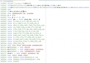
The following BASIC program is used for the performance test. I compressed several statements into a line and removed any spaces to make it as ugly as possible – and to squeeze out the last ounce of performance, but apart from that it should be quite self-explanatory.
This BASIC program as well as the machine language subroutine have been programmed with CBM prg Studio (designed by Arthur Jordison). Thank you very much for providing this software to the community, Arthur!
Currently SetColor, PositionCursor, DrawPixel and PrintCharacter are implemented in the CHRE firmware and seem to work. No serious testing done, yet. DrawLine implementation is work in progress (aka it stinks)…


