RC 2017/04 – PET Testing

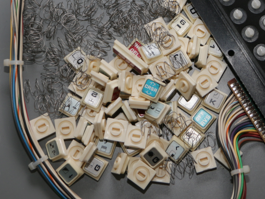
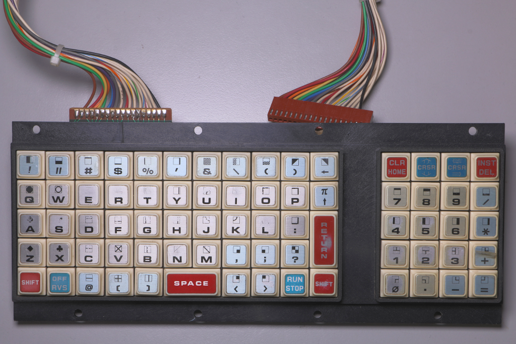
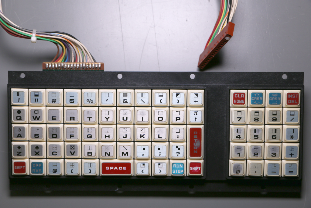
With a reassembled keyboard, a previously repaired CRT and a previously repaired mainboard we’re ready to stick the PET together and fire it up for further testing. 
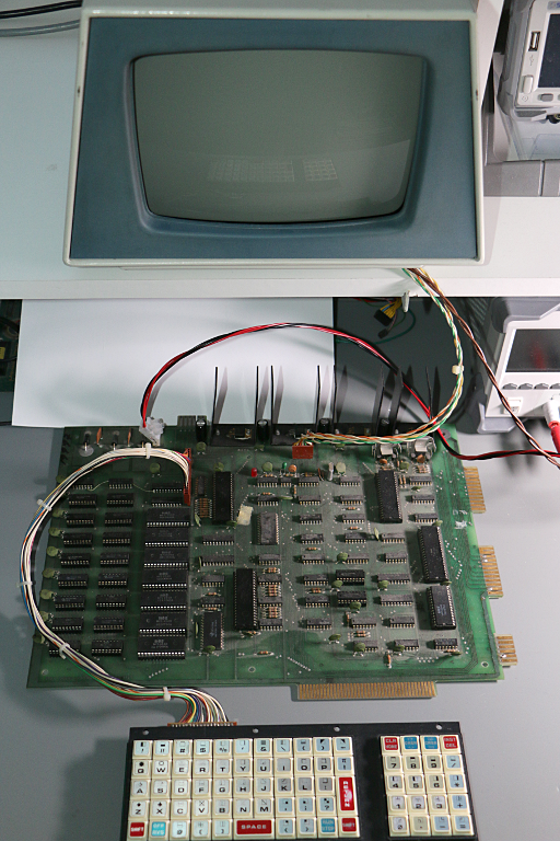
We use separte channels on the power supply for mainboard and CRT and turn Over Current Protection on – just in case…

A piece of white paper behind the mainboard will help to localize any magic smoke trying to escape. No, hopefully not! It’sĀ  just to hide the usual random stuff scattered on a bench.

Well, then! Take a deep breath! Cross your fingers! Push power button #1 (CRT)! Oookaaaay. No arcing. No smoke. OVP did not trip. A current flow of about 130 mA sounds reasonable. So far, so good. Take another deep breath and turn on channel #2 (mainboard)!

Uuaaah!!! I’d like to point out that this is not exactly what I was looking for. But no arcing, no smoke, no OVP trip either. About 2.5 A current flow is ok as well.

To the oscilloscope!

Horizontal sync, vertical sync and pixelstream are looking good, so we can’t blame it on the main circuitry. Oh, great! That means we’ll have to do probing on the CRT circuit board – close to the high voltage area. Any volunteers?

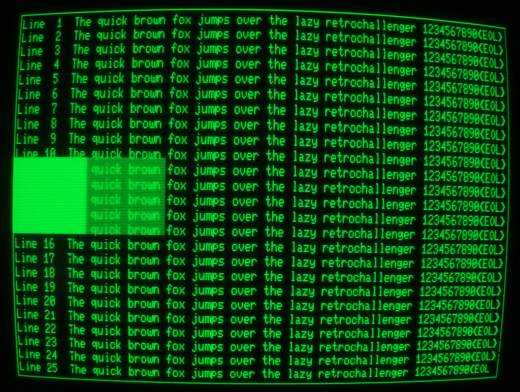
Fortunately it was much easier than I thought. Most errors are sitting in front of the machine, as the saying goes. You bet! I knew that the CRT needed 12 V to operate and that was precise what the power supply was set to. Nothing to complain, right? Well, as soon as I looked at the schematic I realized that the 12 V voltage regulator is situated inside the CRT and not on the mainboard. It’s a standard 7812 type regulator, so we have to add the dropout voltage of 2 V to the regulated output voltage. After changing channel #1 to 14.5 V the PET welcomes the RetroChallenge audience:
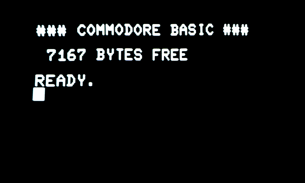
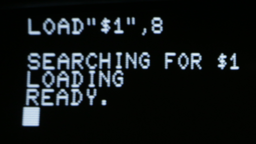
YEAH! That feels good! šŸ™‚ A trivial BASIC program works as intended:

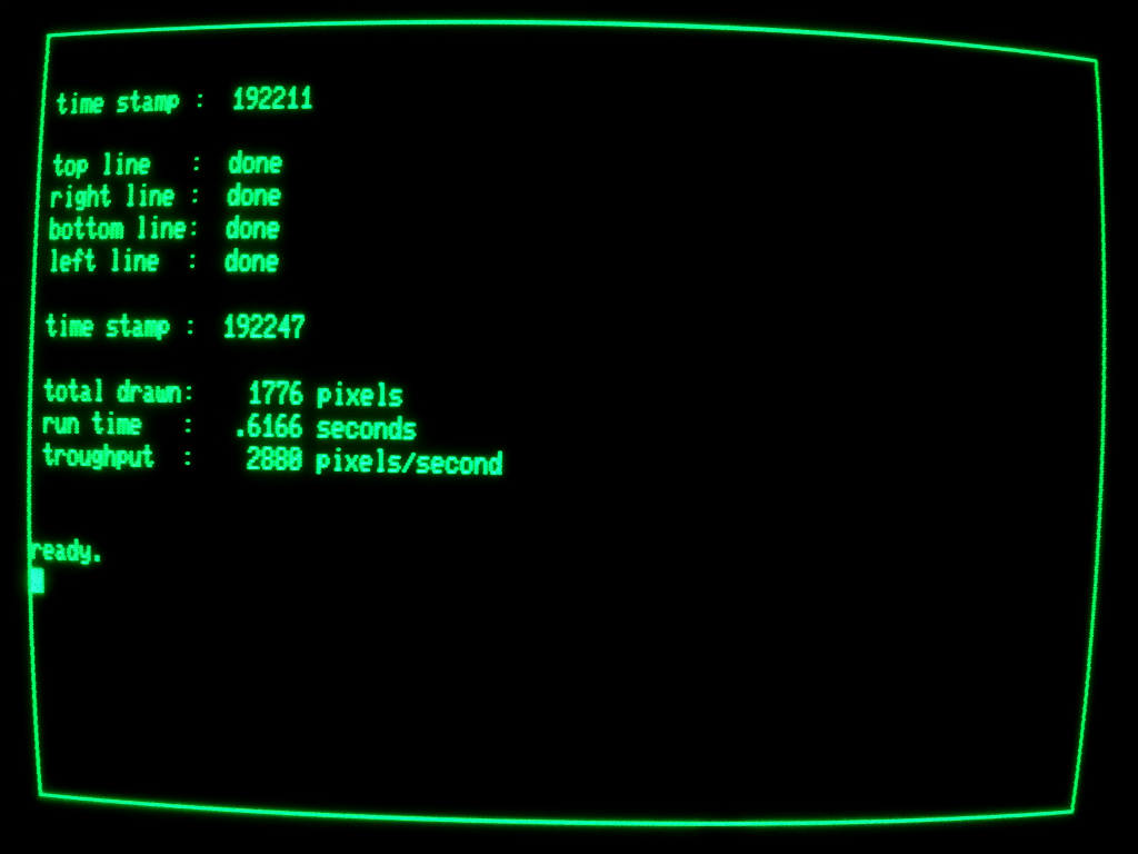
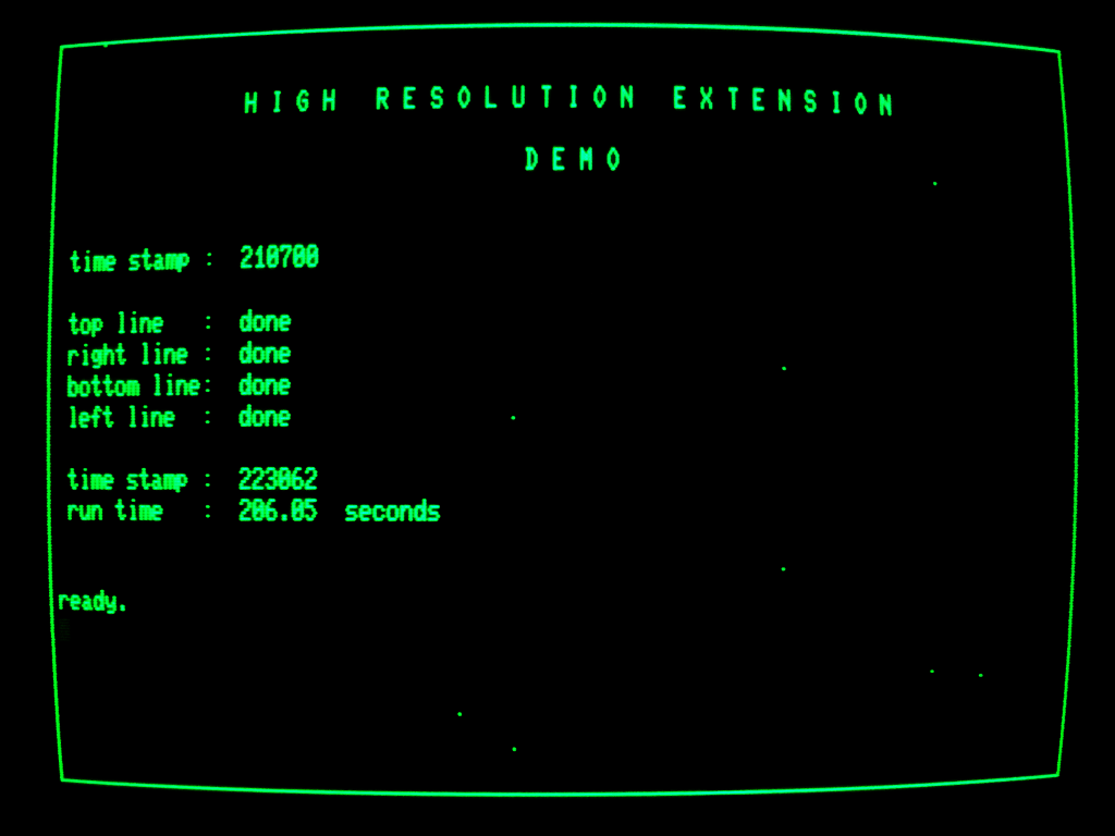
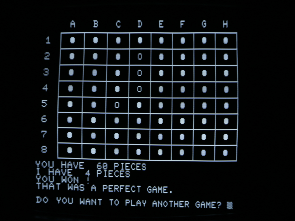
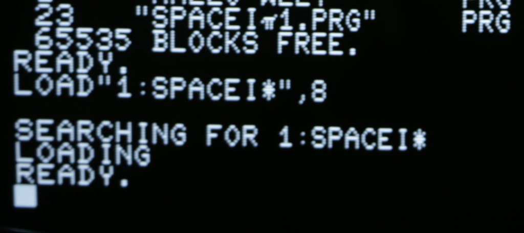
It’s running at cyberspeed <ahem>, so the last digit shows some ghost pixels. I checked the tape interfaces with an external Datassette and both were fine. But all attempts to get a device running on the IEEE-488 bus (aka GPIB) failed. Before we investigate this issue any further, we need to perform some more comprehensive tests:

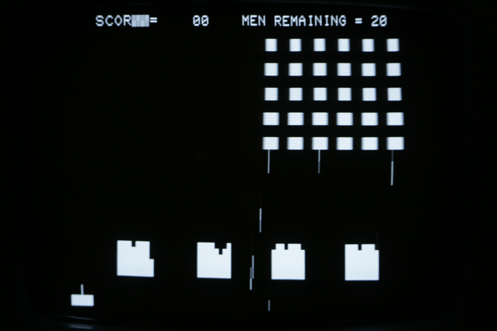
Ahhh, it’s been the golden age when humans were able to outplay computers…

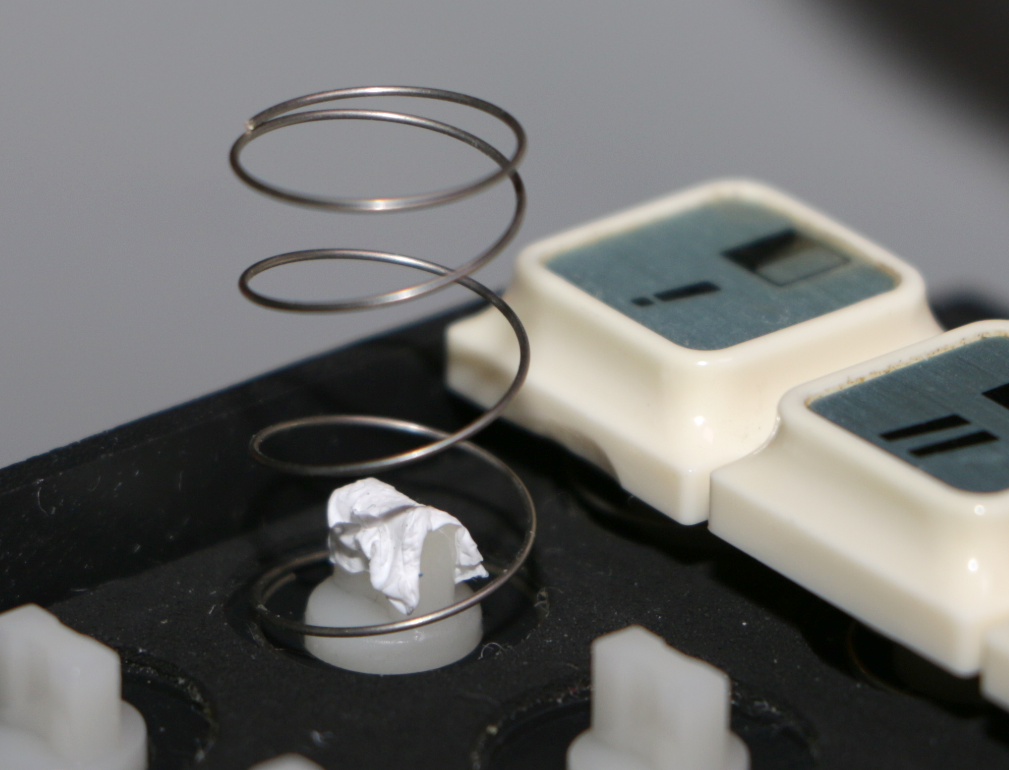
Ok, RetroChallenge is no amusement hall. We have a mission! Let’s track the IEEE-488 issue down! There are two 6520 Peripheral Interface Adapters (PIA) in a PET 2001, one acts as IEEE-488 bus controller, the other one mainly as keyboard controller and as datassette port controller to some extend. Keyboard and datassette ports have been verified. A simple swap should tell if the GPIB PIA is dead. When I had lifted the GPIB PIA out of its socket I found some residue on the pins as well as on the socket.

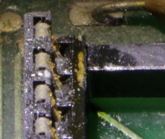
A toothbrush in collaboration with denatured alcohol removed it easily. A quick check (after PIA had been reinserted) verifies we have a working GPIB now! Hurray!


I call that a running system – the PET has been reanimated.Ā  RetroChallenge Mission #1 accomplished.

RC 2017/04 – Keyboard Puzzle

Ok, let’s get started! As the disassembled PET takes a lot of space on the bench, it will be my first goal to put all parts back into the chassis. Most of the issues this computer had when I got it, should have been fixed during the previous repair sessions (which are not part of this RC entry), but it’s more convenient to perform measurements and/or soldering while the mainboard lies on the bench. So testing will go along with the reassembling procedure, just in case something has been overlooked.

Talking to computer systems of the 70s wasn’t like talking to a modern smartphone – we were forced to use a special device named ‘keyboard’ that looked similar to this one:


As you can certainly imagine, it’s been hard work to use such a keyboard, so blood, sweat and tears build up on the device after a while. In this case ‘a while’ translates to ’40 years’ and I was surprised to find only minor deposit on the keycaps…


… but decided to get rid of it anyway. Tissue, denatured alcohol, time and some more sweat got me to the point where the surface started to shine again:


Unfortunately the alcohol partially dissolved the labelling, so I used it only for cleaning the plastics. And to be honest, the whole process was agonizingly boring! It will take a looooong time to choose a suitable detergent for cleaning the top of the keycaps…

During the cleaning it crossed my mind that arranging things diffently might improve the usability of the keyboard.

I really enjoyed this puzzle although I heard a ghostly voice all the time shouting ‘Give me a Q! Give me a W! Give me an E!’ and so on. Can’t remember exactly where I heard this voice in my youth. Sesame Street? Most likely. Everything went well, except the ‘Q’-key. The keycap did not fit and guess what happened? Statler and Waldorf were laughing at me ‘When a spring sprang in spring! <chrrrrhrrhrr><chrrrr>’.

Glueing the keycap to this other light grey thingy wasn’t an option, but a few layers of flimsy PTFE tape made my day.

I’d like to believe that one can tell the difference…

RC 2017/04 – PET/CBM Color Graphic

My entry for RC 2017/04 will be a mingle-mangle of several things that are going through the back of my mind:

The Commodore PET 2001 turns 40 this year and I scored a defective one about a year ago on ebay. Some issues have been fixed already but the system is still disassembled and has to be tested as a whole. I assume the PET would appreciate to be reanimated at its birthday.

The Video Graphics Array (VGA) turns 30 this year. Having a weakness for graphic extensions (see my RC 2015/7 entry) my main entry to RC 2017/04 will be a PET/CBM Color Graphics Extension sending pixels to a VGA display.

The Atmel AVR 8 bit architecture turns 20 this year. So I’ll use this type of MCU for the graphics board.

Celebrating 40 years PET 2001 plus 30 years VGA plus 20 years AVR sum up to 90 years of Retrocomputing. That should comply with the RetroChallenge Rules quite easily.

RC 2016/1 – Let’s try again!

My entry to Retrochallenge 2015/07 was quite successful but left room for improvement. So I’ll take a new attempt based on the experience with the previous entry:

The project for Winter Warmup will be a follow-up to HRE aka High Resolution Extension aka monochrome 648 x 256 pixel graphics board for Commodore PET/CBM 8000 series:

Goal #1: replace the breadboard by a printed circuit board

Goal #2: improve firmware (character support; more sophisticated data transfer protocol; circles)

Goal #3: implement CBM control software as a BASIC extension

Goal #4: add color capabilities in the remaining time (no, just kidding).

Talking about goal #4: What happens when you leave a nerd alone with a full pint of beer and a crazy idea on New Year’s Eve? Yep! He will come up with an even more insane idea!

So this is goal #4 defined and explained in detail:
– add VGA port
– add color mode with 160 x 200 pixel resolution at 8 colors
– add firmware functions similar to monochrome mode
– buy ticket valid for 10 meetings with psychologist

EDIT: Unfortunately I haven’t had time to get this project going. It’s still in my mind, though. To be continued some day …

EDIT: The ‘some day’ will be RetroChallenge 2017/04 and here is the link to my entry.

RC 2015/7 – Follow up #1

A month has past since the end of Retrochallenge 2015/07 and … I miss the feeling! Yep, I miss the Retrochallenge feeling. That is, working on a challenging project just for fun. Specifically working on interesting stuff for ancient computers. Ok, I assume you’re one of the 0.0236986301 ppm of world population who do understand what I’m talking about if you’re reading this at all.

Therefore I won’t wait for RC 2016/01. I’ll continue to work on my RC 2015/07 project and turn the proof of concept into a working prototype. To be honest I already restarted the project and didn’t tell you. šŸ˜‰

Finding the Vsync bug that showed up in the demo video (RC 2015/7 final post) has been the first task. As I have mentioned before it is critical to count every single cycle within the video output routines. And what happens when you work after work ’til late night? You sometimes can’t count anymore! The error was caused by a not equally timed program path. There is a reason why they call an oscilloscope “electronic engineer’s best friend”. Would have been clever to verify the counted cycles with my friend somewhat earlier…

Optimizing the code gave me some additional free cycles so I could increase the resolution from 640 by 250 to 648 by 256. It’s nothing to write home about but the extended resolution allows to draw small symbols outside the CBM text region which might come in handy in certain cases.

One page consumes 648 * 256 / 8 = 20,736 bytes of external SRAM. The size of the installed SRAM is 131,072 bytes (128k * 8 bit). How do we make use of the remaining memory? Several framebuffers! The ATmega162 can address 64k of external SRAM minus 1k internal SRAM minus 256 bytes registers. These 64,256 bytes contain 3 framebuffers and leave 2k for future ideas. The other half of the SRAM chip can be reached by banking. That equals to six independend framebuffers and two 2k free memory blocks in total.

The framebuffers can be used in two modes. In mode 0 all six buffers are orthogonal. In mode 1 only the three buffers in bank 0 are available for drawing while the three buffers in bank 1 are used to implement a second ‘color’. You may call this lower level of brightness ‘dark green’ as well as ‘transparent green’. The following image shows the extended resolution by a border drawn outside the CBM display real estate and explains the meaning of ‘dark/transparent green’.
interlaced02Please take a closer look at the characters ‘T’ in the bottom half of the screen and ‘1’ in ‘Line 21’ as well as the disruption of the right border line. These seem to be side effects of the wild wiring – sometimes present, sometimes absent. EDIT: No, it’s a problem of the CBM mainboard that persists even if I disconnect the HRE completely. Talking about the characters only. The line disruption is most likely a problem of the HRE. And no, it’s not the dust on my camera.

To get the second ‘color’ two associated framebuffers at the same address on different memory banks are used. The video output routine switches between these two buffers at a frequency of 25 Hz. If a pixel at a specific location is set in both framebuffers it will be displayed at full brightness. If it is set in one framebuffer only it will be displayed at half brightness. Due to the fact that CBM text is always displayed at full brightness it will shine through in areas of ‘dark green’.

Unfortunately the applicability of this second ‘color’ is very limited: A refresh rate of 25 Hz implies severe flickering. Adjusting the potentiometer at the back of the screen to reduce overall brightness might help a bit but won’t provide a good display quality.

I plan to modify the user port communication but haven’t come up with a better solution. A first attempt to implement a more sophisticated protocol killed the balanced timing.

RC 2015/7 – Final Post

Ok, Murphy did bug me – as always. I eventually finished a short crapy video that is currently uploading to my Youtube channel. It’s my first video ever and I have no idea if it will be of acceptable quality, but I’m sure you will enjoy my stuttering:

High Resolution Extension demo video

All aims of this RC project have been accomplished.Ā  šŸ™‚Ā  I’m astonished that the wild wiring hasn’t caused any severe problems. Yes, there is some jitter and maybe it’s a result of not having a proper PCB – maybe. And there is a loose contact. That’s it. Not half bad!

And the firmware? Well, as you can see in the video there is an issue with synchronisation when line mode is used. Unfortunately I failed to debug it this day. Drawing procedures that have a “longer” execution time will trigger the error. That’s confusing because both sync routines have been implemented as interrupt service routines (ISR). Some investigation is required here…

Ideas for future development? Yes, sure! Character generator, page switching, sprites, DrawRectangle, DrawCircle, …

Retrochallenge 2015/07 has been great fun! Thanks for having me! Looking forward to RC2016/01!Ā  šŸ™‚


RC 2015/7 – Home Straight

Engineer’s Log, Labdate 0730.12. We finally reached Warp 5.0! Too bad this starship has been shut down long since.

Yesterday I met target #6 of my Retrochallenge project: A very basic Graphical Processing Unit has been implemented. Besides its primary tasks (framebuffer handling, host communication, set pixel at x/y position) the microcontroller features a DrawLine command now. This results in a tremendous speedup:

hredemo07

We went from 159 seconds (see previous post) to 0.62 seconds! Instead of sending 1776 single SetPixel commands to the HRE we’re now sending only 4 DrawLine commands. This way we overcome the poor BASIC performance.

The acceleration would be even more impressive if we would compare diagonal lines because in that case we’d have to do some additional calculation in BASIC. I implemented a complete Bresenham line drawing algorithm in the HRE firmware so diagonal lines are supported.

The microcontroller has still plenty of flash memory left for future expansion (about 79%). But I have attained all goals for this Retrochallenge and prefer to spend more time in bed in the upcoming nights. šŸ˜‰

I’m going to write a demo and to shoot a video in the remaining hours until RC2015/07 ends – provided that Murphy won’t bug me.

RC 2015/7 – Dances With Pixels #3

Engineer’s Log, Labdate 0728.20. Warp 4.8! We’re getting close.

After a close fight against Murphy I finally won the day: The Commodore CBM 8296 is talking to the HRE via the userport. This small BASIC program demonstrates how the communication is handled on the CBM side. It draws a border around the screen in this order:

(x, y) Ā Ā  0, 0 –> 639, 0 –> 639, 249 –> 0, 249 –> 0, 0

hredemo01hredemo02

Parts of the program have been squeezed by some methods we used in the early 80th to reduce execution time. These tricks reduced not only the readability of the program but also the runtime from 206 seconds …
hredemo03
… to 159 seconds …
hredemo04
which is still very slow.

If my cell phone cam is able to shoot a video of the program output there will be a final comparison of this pixel by pixel output and the accelerated line output I plan to implement tomorrow.

RC 2015/7 – Dances With Pixels #2

Engineer’s Log, Labdate 0726.15. We are traveling at warp 4.5 now. Scott and Spock are still trying to reach warp 5.

Found the missing pixels. They have been buried under some missing NOP instructions. Hmm, ok, it’s nearly impossible to bury anything under something that is missing but I managed it somehow. šŸ˜‰

Now HRE has full resolution of 640 x 250 = 160,000 pixels!

A simple interface should read commands from the CBM userport. How do we implement this feature? It depends on the time between successive commands and on the transmission time for a single command. I’ll write a small transmit loop in BASIC and measure the execution time. A datassette has the honorable duty of being responsible for a save and reliable storage.

I don’t care about command structure at this stage. All I want to measure is the time for the fastest possible change of signal levels at the userport (BASIC only). Will the execution speed change if we put two BASIC statements in a single line?

1000 POKE 59459,255
1010 POKE 59471,255:POKE 59471,0
1020 POKE 59471,255
1030 POKE 59471,0
1040 GOTO 1010

usrport01Wow! 7.281 milliseconds! What a blazing speed! That equates to a bandwidth of more than 137.343 bytes/s! Eat your heart out Nvidia!

Putting two statements in a single line doesn’t make any difference.

Ok, let’s assume the 6502 is going to train for CPU olympics. Hence, further calculation will be based on a value of 5 ms to be on the safe side. If we sample the userport at each HSYNC interrupt we get more than 80 samples per level change. That’s more than adequate. Currently there are about 170 free cycles at the beginning of the HSYNC ISR so I intend to handle the userport communication there. It’ll be somewhat challenging because the HSNC ISR must be cycle exact. So what? May I remind you that this is a retroCHALLENGE entry?

Now we should think the protocol through. The absolute minimum number of bytes per command (without considering compression) will be four:

1Ā  byte for instruction (e.g.Ā  1 = SetPixel, 2 = MoveCursor, 3 = DrawLine, …)
2 bytes for X coordinate
1 byte for Y coordinate

Unfortunately the HRE wouldn’t be able to identify the single bytes. For example the command SetPixel(256,1) will translate to $01 $01 $01 $01. Not a single bit does change during the whole data transfer! How do we separate the bytes?

We’ll use only 5 bits of a byte for data and 3 bits for synchronisation. That adds some complexity to the protocol which reduces bandwith even more but we can strive for speed in an upcoming Retrochallenge.Ā  šŸ˜‰

The following table of the three most significant bits shows the unique coding of each byte:

000 => command
001 => X-coordinate low
010 => X-coordinate high
011 => Y-coordinate low
100 => Y-ccordinate high
101 => future expansion
110 => future expansion
111 => future expansion

So we have to transmit a total of five bytes per command.

Looking forward to my first non trivial BASIC program since the 80th.Ā  šŸ™‚