RC 2017/10 – Schematic

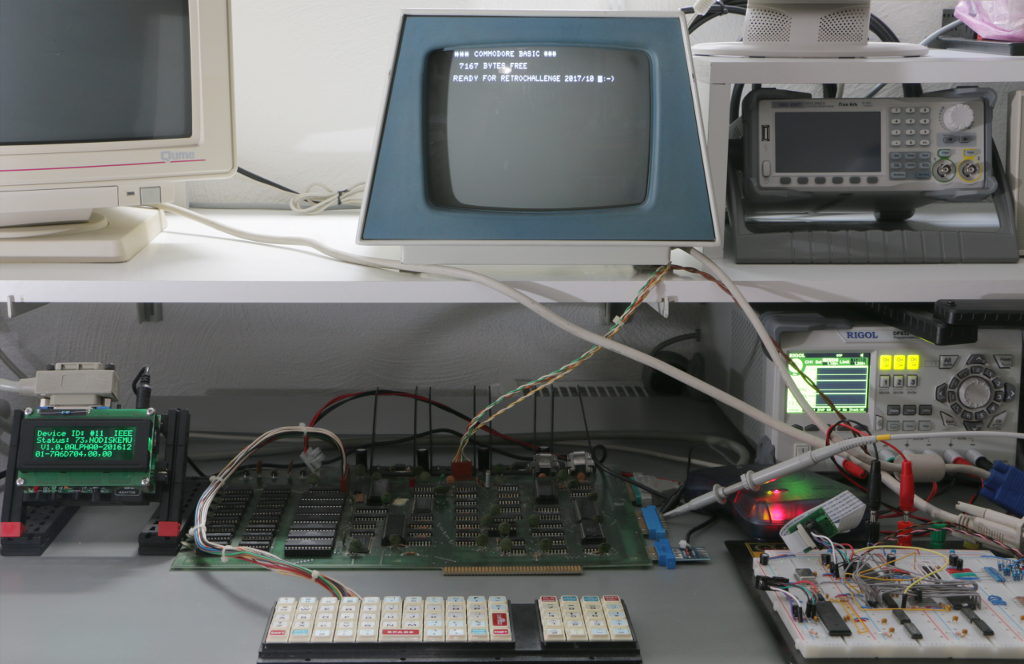
Now that the graphics circuit seems to work, I should give you an overview of the current state of the hardware. Please match this picture of the breadboard
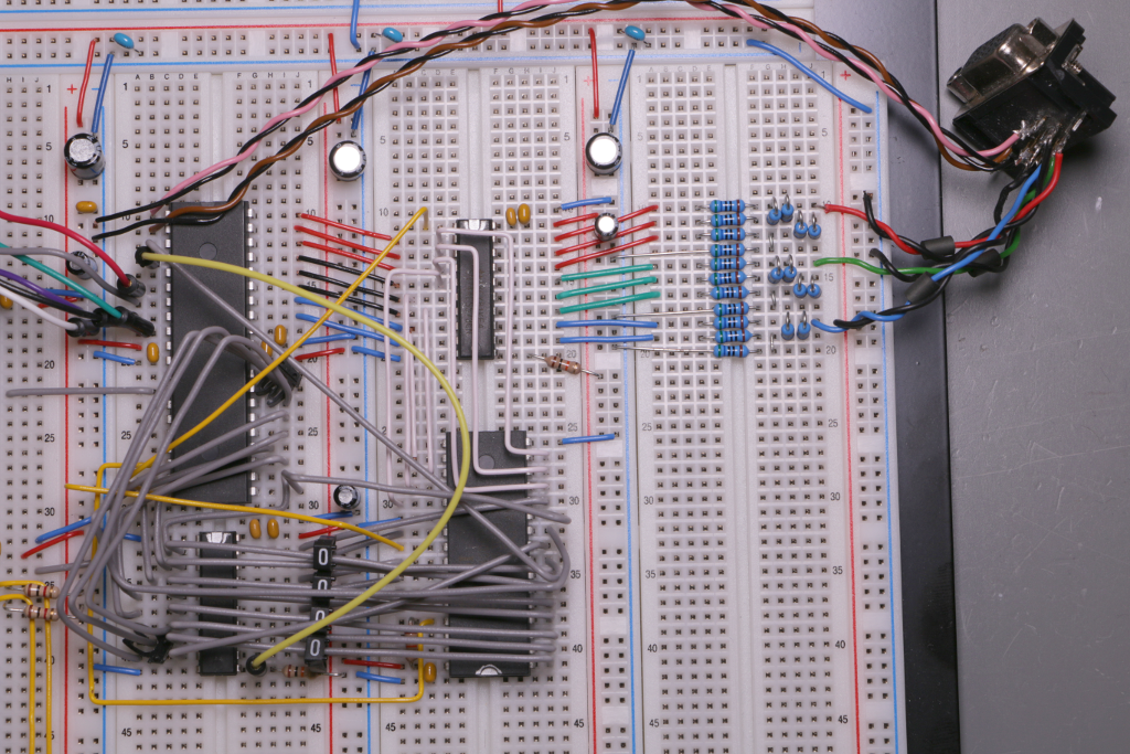
with this

preliminary schematic

The position of the components on the breadboard is roughly reflected in the circuit diagram.

VGA synchronising is handled by PB0 (horizontal sync, pink wire) and PB1 (vertical sync, brown wire).

Latch U2 separates the pixel data bus (Color0..7) from the digital to analog converter during the blanking periods when the microcontroller sends pixel data from Port A to the SRAM. U2 is controlled by PD6. SRAM read/write mode is controlled by PD4.

The address bus is partly multiplexed. PB2 selects the most significant address bit (Addr18). PB3 switches latch U3 into transparent mode, then Port C puts address bits 10 to 17 on the bus, then PB3 switches U3 into latched mode, then Port C puts address bits 2 to 9 on the bus and PD7 / PD5 deliver Addr0 / Addr1.

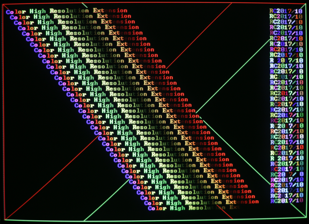
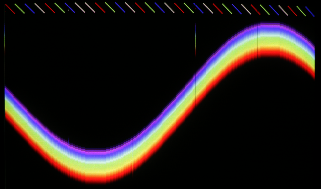
While streaming pixels from SRAM to the screen Port A is in high impedance state and U2 in transparent mode. Three simple R2R resistor ladders convert the digital color information into analog voltages. Eight shades of red, eight shades of green and four shades of blue make 256 colors in total.

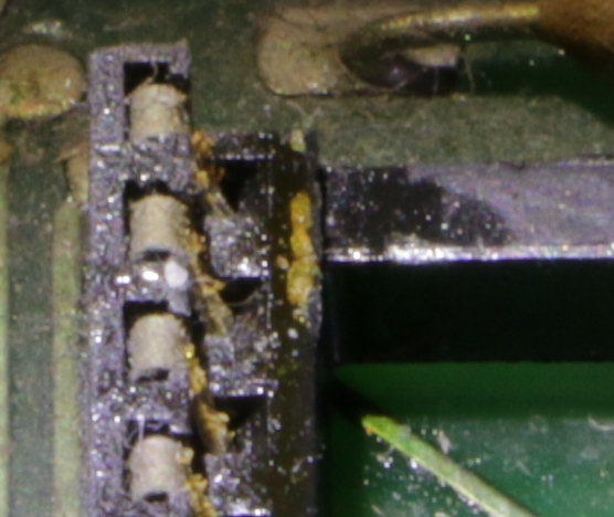
I haven’t decided how to connect to the PET yet. I would like to utilize a shift register in the 6522 interface chip as I have two serial ports available on the ATmega, but unfortunately the 6522 has at least one major bug. From what I’ve read so far it seems that the error only occurs when an external clock is used. Exhaustive tests have to be performed, I’m afraid. Time to play with the EEs best friend… 😉


RC 2017/10 – MARVEL !!!

Please excuse the lurid headline. I’m overwhelmed with emotion! I was already soooo close to the ultimate goal at the end of spring-time RetroChallenge – but couldn’t see it!

This evening, while exploring sourcecode and breadboard circuit for the first time after several month, the scales fell from my eyes!

After some minor changes this really simple circuit now displays 640 by 480 pixels at 256 colors on the VGA screen!!!

Well, it’s slow as a footsore snail on sleeping pills, but that doesn’t diminish my rapture.  🙂


RC 2017/10 – Getting started

Ok, I finally found some time to get the project started. Better late than never! Not much to report, though. Just the usual tasks before real work can take place:

  • create space on the workbench
  • rake PET and breadboard up
  • find documentation (if available at all)
  • connect everything
  • download/install/configure toolchain
  • cupato (cheer up, pray and turn on)
  • REPEAT pull_a_long_face UNTIL all_bugs_fixed == true

I was pressed for time (aka lazy) last RetroChallenge, so I failed to realize that it would have been a fantastic idea to clean not only the 6520 socket but every chip and socket on the contaminated PET mainboard. The PET refused to start the BASIC interpreter and soft-landed in TIM. Tough luck! Fortunately a retro computing nerd agreed to do the cleaning – grumpily…

The PET seems to be ok now but the breadboard lives up to it’s name – not a single pixel is displayed on the VGA monitor. Monitor is ok when connected to a PC. Maybe the firmware version does not fit the last modifications of the circuit? To be honest, I probably missed to document the last steps as I hoped to continue the project on the next day. Apparently, it took about five month – and memory fades away…

In case you’re new to this project (or your memory is teasing you as mine does in this case), please consider (re)reading the archived blog entries of RC 2017/04 where I discussed some project basics. Otherwise it might be difficult to follow this ongoing development. Anyway, please feel free to put your questions into the comments. Moderated comments are used to prevent spamming, so it’ll take some time before your comment gets published.

RC 2017/10 – PET/CBM Color Graphic again

At the beginning of RC 2017/04 I promised my dearly beloved PET 2001 that it will be transformed into a Color-PET this year. I stand by my promise.

Spring-RetroChallenge lead to a color graphic system on a breadboard. It was capable of displaying 320 by 240 pixels at 256 colors on a VGA monitor. Besides a few quirks it worked quite reliable but was not connected to the PET at all.

During this RetroChallenge I plan to get rid of the remaining bugs, integrate the graphic system into the PET and write a BASIC extension that supports graphic primitives like DrawPixel, DrawLine, ClearScreen, etc.