RC 2018/04 – Kick Off

Any home computer needs at least an input device, a computing device and an output device. I plan to use a keyboard as input, an ATmega1284 microcontroller with some external SRAM as the computing device and a VGA display as output.

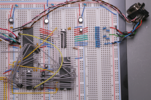
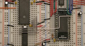
I happen to have a working VGA color graphics circuit (as a result of my RC 2017/10 entry) that I’m going to recycle for this home computer project. First step is to compress its breadboard footprint:

Main components from left to right:
– 25 MHz TTL oscillator
– top: ATmega1284P microcontroller, bottom: 74ALS573 latch
– top: 74ALS573 latch, bottom: IS61C5128AS 512K x 8 25ns SRAM
– 21 resistors (560 ohm) forming 3 digital to analog converters
plus several capacitors and pull up/pull down resistors.

Meaning of wire colours:
– black: ground
– red: supply voltage (+5V DC) or data lines for the red color path
– green: data lines for the green color path
– blue: data lines for the blue color path
– orange: system clock (25 MHz)
– purple: address lines A0, A1, A2
– grey: address lines A3 to A10
– white: address lines A11 to A18
– yellow: control lines (like chip enable, output enable, …)
– pink: horizontal sync
– brown: vertical sync

To be honest, I’m violating rule #1 here: The external SRAM is a SMD chip on a breakout board. I simply couldn’t find any DIP SRAM with an access time of 40ns or less. The RC2017/10 project successfully used a 55ns chip well beyond its specifications, but only when wired in a special way. The MCU is also overclocked (max. clock speed 20 MHz specified) but it runs easily at more than 30 MHz, so I consider 25 MHz to be save.

Adding wires for address lines…

Ok, I need something to eat now, so I’m going to declare this circuit to be the minus56 home computer, version 0.01 alpha.  😉

Moderated comments are used to prevent spamming,
so it’ll take some time
before your comment gets published.

RC 2017/10 – PET Comm #3

Just to make sure the protocol is okay, a small BASIC program sends six frames of data per pixel representing X coordinate, Y coordinate and Color. It’s easy to convert the values into 6 bit wide words:

Xhigh = INT(X/64) : Xlow = X-XH*64      (  X [0..639]  )
Yhigh = INT(Y/64) : Ylow = Y-YH*64      (  Y [0..479]  )
Chigh = INT(C/64) : Clow = C-CH*64      (  C [0..255]  )

Data is sent in the order Xhigh, Xlow, Yhigh, Ylow, Chigh, Clow. There is no function identifier transfered to keep it as simple as possible for the moment. Therefore the CHRE executes always the SetPixel(x,y,c) function to draw a single pixel at the coordinates x,y in the color c.

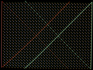
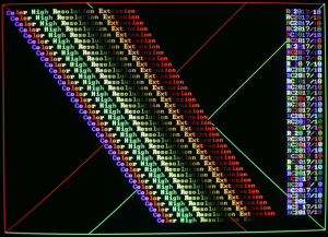
The following image shows some red and green lines that are coded into the CHRE firmware. This test pattern is written to the framebuffer when the CHRE is ready to receive serial data. The colorful small lines that are evenly spread are drawn pixel by pixel of the received data packets:

I’m very happy with the result. No missing pixels, no pixels out-of-line.

It took ages to render this image at a rate of 5 to 6 pixels per second. That was to be expected, though. BASIC is way too slow for this task. For the final version I’ll write all communication related code in Assembler.

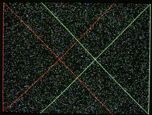
By the way: Have you ever wondered why some of your BASIC games were pretty predictable despite the fact you used the random number function? Well, I did back in the day! The next picture shows random pixels:

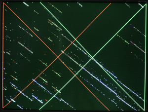
And this picture shows random pixels, too:

Both BASIC programs were identical, with the exception of the parameter for the random number function: RND(1) vs. RND(0)
All necessary information was in the manual of the 8xxx series, but as far as I remember we never had a PET 2001 manual in school. Maybe our teacher hid the manual to hold all the cards? Pointless! 🙂


RC 2017/10 – PET Comm

I had a nightmare last night. The oscillogram of the phase2 clock (see previous post) turned into a nasty saw and cut the mainboard of my PET in half. I definitely should go and find the cause of this weird thingy that pretends to be a rising edge, but that investigation might take a while longer. To get on with the main project, I’ll mimic the PET’s own pragmatic way for a moment: Ignore! Business as usual!

Now that we have found the 6522 shift register working even at high speed, it should be suitable to transmit data to the CHRE. The PET also needs a way to check if the CHRE is ready to receive (more) data. We add a binary busy/ready signal and end up with a three wire connection:

PET userport pin 11 <—-> CHRE ATmega pin 11, GND, black
PET userport pin M,   —-> CHRE ATmega pin 14, DATA, blue
PET userport pin B,  <—-   CHRE ATmega pin 15, BUSY, yellow

Have you ever experienced the resolution cancellation phenomenon? No, I’m not talking about politics here. What I mean is: You start with the intention to write a serial communication protocol, but get distracted by some other code as soon as your IDE pops up? I went down the rabbit hole of performance optimization. Yes, I know the rule. Don’t optimize your code in an early stage! I just couldn’t resist.

To make a long story (aka coding&debugging session) short: The time to produce this demo output

has been reduced from 10 minutes to 16 seconds. That’s still slow as a snail, but now it’s a snail on amphetamine! 😉

Provided that I did count accurate, the screen content is built up of 153,728 pixels. 153,728 pixels divided by 16 seconds equals 9,608 pixels per second. Back to serial communication: Drawing a single pixel is the most basic function the CHRE has to provide. And it’s the worst case in terms of the communication protocol as well: Only one pixel per function call. How many DrawPixel function calls can we transfer over the serial link at a bit rate of 250 kbit/s ?

A serial frame consists of one start bit, six data bits and one stop bit. Without further encoding, we would need seven frames:

1 frame function identifier (using 6 bits),
2 frames X coordinate (using only 10 bits out of 12),
2 frames Y coordinate (using only 9 bits out of 12),
2 frames color (using only 8 bits out of 12).

These seven frames correspond to 56 bits (start and stop bits included). So we can transfer 4,464 frames per second (250,000 divided by 56). That’s insufficient, isn’t it? Well, it depends.

The CHRE pixel rate is already very slow. The ATmega is currently using nearly all of its processing power to handle the framebuffer and do the rendering. We’ll have to steal some clock cycles from the rendering to implement a serial protocol, hence reduce the amount of pixels the CHRE can render per second. Another aspect is the real application. A few thousand pixels per second may be adequate if the PET does analysis of a math function and curve sketching. A 3D ego shooter is out of reach, though.

Coding time…

RC 2017/10 – 6522 inspection

In addition to the IEEE-488 bus the Commodore PET/CBM series features an 8-bit parallel interface named Userport. A single 6522 Versatile Interface Adapter (VIA) provides bidirectional I/O lines, two 16-bit timers and an 8-bit shift register for serial communications.

The monochrome High Resolution Extension (RC 2015/07) used a parallel protocol for Userport communication. In theory we could use it with CHRE as well since there are eight free I/O pins left on the ATmega (four pins of the programming header included). But I hope to keep a few extra clock cycles on the ATmega if I use its USART (Universal Synchronous/Asynchronous Receiver/Transceiver) hardware support for serial communication.

Only a few cycles? So why bother about it at all? Well, lets compare the requirements:

HRE:
resolution 640 by 250 pixel
one BIT per pixel (monochrome)
20,000 bytes per frame
50 frames per second
data transfer rate about   1 MByte per second

CHRE:
resolution 640 by 480 pixel
one BYTE per pixel (256 colors)
307,200 bytes per frame
60 frames per second
data transfer rate about 18 MByte per second

The CHRE microcontroller is somewhat more stressed due to this tiny difference. It has to spend a lot more processing power on the job. This leaves us with only a small amount of time to

  • do PET communication,
  • decode, verify and dispatch the received drawing commands,
  • do the rendering.

For example, it took nearly ten minutes (!) to render the screen content that I posted the other day. Granted, there is room for firmware improvement, but it definitely makes sense to be picky about the use of clock cycles.

It is said that the 6522 VIA shift register will lose a bit if an externally supplied shift clock edge falls within a few nanoseconds of the falling edge of the internal clock. So maybe the shift register won’t bug me if the internal I/O clock is used?  I’m sure there is a comprehensive discussion about this issue somewhere on the internet, but I couldn’t find it. Oookay, you’ve got me! I’ve done no more than a superficial search, because I’d like to play with the scope. The official statement is: I need to know if the VIA in my PET is functional at all. 😉

We don’t have to comply with any standard here, so we start the test with a bit rate of 2,000 bit/s. The VIA setup is done by a short BASIC program:
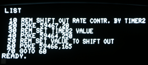
Let’s look at the clock signal first:

Ch1:  internal I/O clock (phase 2)
Ch2:  output shift register (bitstream)
S1:  decoded bitstream (binary)
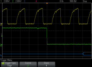
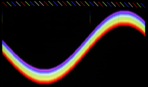
Ohuuu, that’s not exactly the most rectangular square wave I’ve ever seen, I’m afraid. However, surprisingly the VIA doesn’t seem to care! The bit stream looks quite good at first glance:
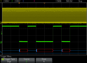
Yep, there’s a problem with the second glance: Now you wish you had stuck to the first one. Anyway, we have to note the absence of any decoded data. The empty red boxes are a polite indication that

a) the VIA is really faulty,
b) the creature in front of the scope made a suboptimal decision.

Make an educated guess…

… It’s  b).  Using 8 bit data wasn’t clever.

The shift register in this VIA is just an 8 bit shift register, no complete UART/USART. It does not send a leading start bit and does not send a trailing stop bit either. Without a start bit the scope cannot detect the beginning of a frame and therefore cannot decode the bitstream.

A slight modification to the BASIC program reduces the usable data length to six bits. The answer to all questions is stored in variable D (binary 00101010). We multiply by 2 (result: binary 01010100) and add 1 (result: binary 01010101). The MSB is now zero (aka start bit) and the LSB is one (aka stop bit).

Now the scope decodes the data:
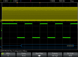
To find out if there is some kind of rare glitch we use the mask test function of the scope:
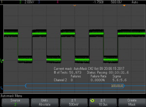
I’ll call that a promising result. When cranking up the bit rate to 250 kbit/s we get the same good result. So we may assume that at least an unidirectional serial communication is possible…
 

RC 2017/10 – Schematic

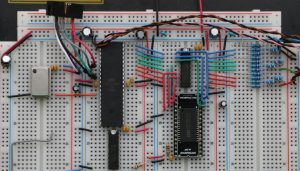
Now that the graphics circuit seems to work, I should give you an overview of the current state of the hardware. Please match this picture of the breadboard

with this

preliminary schematic

The position of the components on the breadboard is roughly reflected in the circuit diagram.

VGA synchronising is handled by PB0 (horizontal sync, pink wire) and PB1 (vertical sync, brown wire).

Latch U2 separates the pixel data bus (Color0..7) from the digital to analog converter during the blanking periods when the microcontroller sends pixel data from Port A to the SRAM. U2 is controlled by PD6. SRAM read/write mode is controlled by PD4.

The address bus is partly multiplexed. PB2 selects the most significant address bit (Addr18). PB3 switches latch U3 into transparent mode, then Port C puts address bits 10 to 17 on the bus, then PB3 switches U3 into latched mode, then Port C puts address bits 2 to 9 on the bus and PD7 / PD5 deliver Addr0 / Addr1.

While streaming pixels from SRAM to the screen Port A is in high impedance state and U2 in transparent mode. Three simple R2R resistor ladders convert the digital color information into analog voltages. Eight shades of red, eight shades of green and four shades of blue make 256 colors in total.

I haven’t decided how to connect to the PET yet. I would like to utilize a shift register in the 6522 interface chip as I have two serial ports available on the ATmega, but unfortunately the 6522 has at least one major bug. From what I’ve read so far it seems that the error only occurs when an external clock is used. Exhaustive tests have to be performed, I’m afraid. Time to play with the EEs best friend… 😉


RC 2017/10 – MARVEL !!!

Please excuse the lurid headline. I’m overwhelmed with emotion! I was already soooo close to the ultimate goal at the end of spring-time RetroChallenge – but couldn’t see it!

This evening, while exploring sourcecode and breadboard circuit for the first time after several month, the scales fell from my eyes!

After some minor changes this really simple circuit now displays 640 by 480 pixels at 256 colors on the VGA screen!!!

Well, it’s slow as a footsore snail on sleeping pills, but that doesn’t diminish my rapture.  🙂


RC 2017/10 – Getting started

Ok, I finally found some time to get the project started. Better late than never! Not much to report, though. Just the usual tasks before real work can take place:

  • create space on the workbench
  • rake PET and breadboard up
  • find documentation (if available at all)
  • connect everything
  • download/install/configure toolchain
  • cupato (cheer up, pray and turn on)
  • REPEAT pull_a_long_face UNTIL all_bugs_fixed == true

I was pressed for time (aka lazy) last RetroChallenge, so I failed to realize that it would have been a fantastic idea to clean not only the 6520 socket but every chip and socket on the contaminated PET mainboard. The PET refused to start the BASIC interpreter and soft-landed in TIM. Tough luck! Fortunately a retro computing nerd agreed to do the cleaning – grumpily…

The PET seems to be ok now but the breadboard lives up to it’s name – not a single pixel is displayed on the VGA monitor. Monitor is ok when connected to a PC. Maybe the firmware version does not fit the last modifications of the circuit? To be honest, I probably missed to document the last steps as I hoped to continue the project on the next day. Apparently, it took about five month – and memory fades away…

In case you’re new to this project (or your memory is teasing you as mine does in this case), please consider (re)reading the archived blog entries of RC 2017/04 where I discussed some project basics. Otherwise it might be difficult to follow this ongoing development. Anyway, please feel free to put your questions into the comments. Moderated comments are used to prevent spamming, so it’ll take some time before your comment gets published.

RC 2017/10 – PET/CBM Color Graphic again

At the beginning of RC 2017/04 I promised my dearly beloved PET 2001 that it will be transformed into a Color-PET this year. I stand by my promise.

Spring-RetroChallenge lead to a color graphic system on a breadboard. It was capable of displaying 320 by 240 pixels at 256 colors on a VGA monitor. Besides a few quirks it worked quite reliable but was not connected to the PET at all.

During this RetroChallenge I plan to get rid of the remaining bugs, integrate the graphic system into the PET and write a BASIC extension that supports graphic primitives like DrawPixel, DrawLine, ClearScreen, etc.