What if personal computers wouldn’t have displaced home computers?
What if the number of software abstraction layers wouldn’t have exceeded the number of CPU pins?
What if the time to market had not been favoured over flawlessness?
Don’t panic! I don’t want to start several flame wars in parallel here. I just lack a justification for another crazy project and these questions should confuse people so that they don’t ask why (aka Captain Jack Sparrow Principle): I’m going to build a home computer from scratch – just for the heck of it. Nothing like the boring Pi + Linux + WallpaperOfMyCat stuff and unfortunately nothing like the awesome MOnSter 6502 <kneel down>. It’ll be something in between.
So, what is my conception of a home computer?
1. based on electronic parts available to mere mortals
2. modular, expandable and (hopefully) easy to understand design
3. colour graphics and sound
4. SD card storage
5. integrated operating system and programming language
6. favour flawlessness over featuritis
7. good technical documentation
Given the limited time, what are my goals for this RetroChallenge?
I’m toying with the idea to build a computer from scratch for ages. “No time for a project of this dimension” has been my excuse all the time. Essentially, that’s true. So, what is the point of a never ending story? Well, the journey is the reward.
Seriously, there is only one goal: To get this project started!
The above list is pretty vague. So, let’s concretise:
1. Leaded components only, as I love prototyping on breadboards. As few different components as possible. As few special / highly integrated hardware as possible. All components must be available in single digit quantities.
2. Each function module in a separate circuit block. For example, video controller and sound controller will reside on separate MCUs, even if they would easily fit into one.
3. You don’t expect a home computer without graphics or sound, don’t you!!!
4. SD cards are common, cheap, robust and fairly easy to connect, so why not?
5. That’s a difficult one. I want a home computer with batteries included, but developing an operating system, an editor and an interpreter/compiler isn’t precisely a trivial task, even if the functionality would be fairly basic. Let’s discuss this topic when the hardware is already running…
6. This is a hobby project, so I don’t have to worry about marketing. I appreciate any serious suggestion (well, most likely I’m the only nerd who enjoys this kind of endeavour, but in case you happen to be my twin from another universe, please feel free to join the adventure and give me a shout at universe42.galaxy484027.solarsystem925482537.planet3.hominids. globalcom.twitter.username: @minus56bits), but won’t implement features just for the sake of another NEW sticker.
7. Yeah, ok. You already know that this isn’t going to happen, don’t you. At least not in the course of this RetroChallenge. The idea is to support people who would like to get into embedded systems. One can certainly argue about whether the term ’embedded system’ is appropriate in this context, but in my opinion programming is ’embedded’ as soon as you do it on the bare metal.
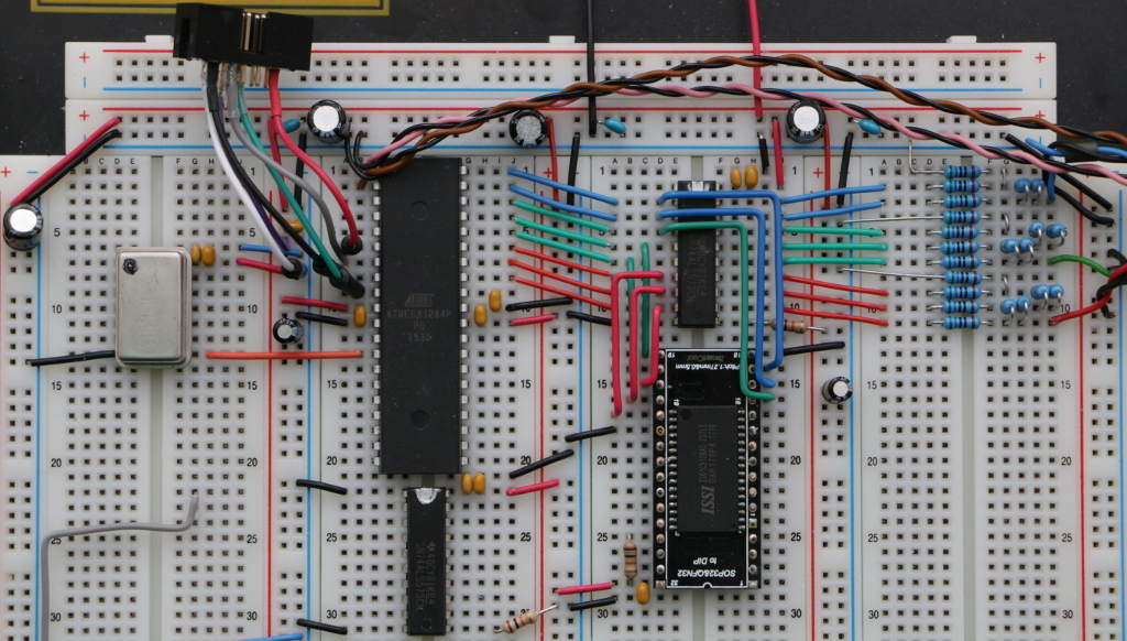
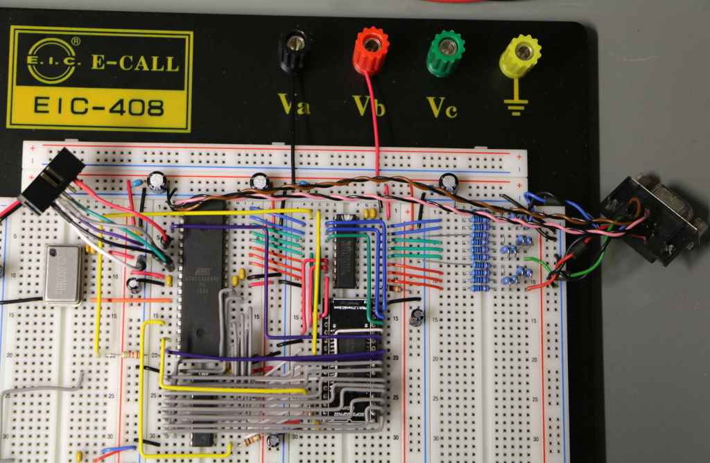
Ok, heading over to the breadboard…
Moderated comments are used to prevent spamming,
so it’ll take some time
before your comment gets published.
 and the firmware has been restructured to free a few cycles. Hopefully. Tests required. It still supports full color graphics at a resolution of 307.200 pixels (640*480) and a color depth of 8 bit (256 colors per pixel).