In addition to the IEEE-488 bus the Commodore PET/CBM series features an 8-bit parallel interface named Userport. A single 6522 Versatile Interface Adapter (VIA) provides bidirectional I/O lines, two 16-bit timers and an 8-bit shift register for serial communications.
The monochrome High Resolution Extension (RC 2015/07) used a parallel protocol for Userport communication. In theory we could use it with CHRE as well since there are eight free I/O pins left on the ATmega (four pins of the programming header included). But I hope to keep a few extra clock cycles on the ATmega if I use its USART (Universal Synchronous/Asynchronous Receiver/Transceiver) hardware support for serial communication.
Only a few cycles? So why bother about it at all? Well, lets compare the requirements:
HRE:
resolution 640 by 250 pixel
one BIT per pixel (monochrome)
20,000 bytes per frame
50 frames per second
data transfer rate about 1 MByte per second
CHRE:
resolution 640 by 480 pixel
one BYTE per pixel (256 colors)
307,200 bytes per frame
60 frames per second
data transfer rate about 18 MByte per second
The CHRE microcontroller is somewhat more stressed due to this tiny difference. It has to spend a lot more processing power on the job. This leaves us with only a small amount of time to
- do PET communication,
- decode, verify and dispatch the received drawing commands,
- do the rendering.
For example, it took nearly ten minutes (!) to render the screen content that I posted the other day. Granted, there is room for firmware improvement, but it definitely makes sense to be picky about the use of clock cycles.
It is said that the 6522 VIA shift register will lose a bit if an externally supplied shift clock edge falls within a few nanoseconds of the falling edge of the internal clock. So maybe the shift register won’t bug me if the internal I/O clock is used? I’m sure there is a comprehensive discussion about this issue somewhere on the internet, but I couldn’t find it. Oookay, you’ve got me! I’ve done no more than a superficial search, because I’d like to play with the scope. The official statement is: I need to know if the VIA in my PET is functional at all. 😉
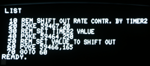
We don’t have to comply with any standard here, so we start the test with a bit rate of 2,000 bit/s. The VIA setup is done by a short BASIC program:
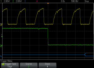
Let’s look at the clock signal first:
Ch1: internal I/O clock (phase 2)
Ch2: output shift register (bitstream)
S1: decoded bitstream (binary)
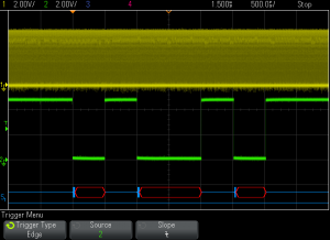
Ohuuu, that’s not exactly the most rectangular square wave I’ve ever seen, I’m afraid. However, surprisingly the VIA doesn’t seem to care! The bit stream looks quite good at first glance:
Yep, there’s a problem with the second glance: Now you wish you had stuck to the first one. Anyway, we have to note the absence of any decoded data. The empty red boxes are a polite indication that
a) the VIA is really faulty,
b) the creature in front of the scope made a suboptimal decision.
Make an educated guess…
… It’s b). Using 8 bit data wasn’t clever.
The shift register in this VIA is just an 8 bit shift register, no complete UART/USART. It does not send a leading start bit and does not send a trailing stop bit either. Without a start bit the scope cannot detect the beginning of a frame and therefore cannot decode the bitstream.
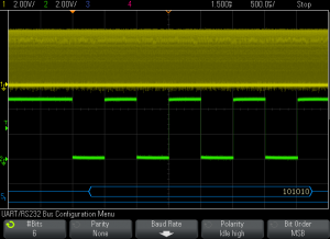
A slight modification to the BASIC program reduces the usable data length to six bits. The answer to all questions is stored in variable D (binary 00101010). We multiply by 2 (result: binary 01010100) and add 1 (result: binary 01010101). The MSB is now zero (aka start bit) and the LSB is one (aka stop bit).
Now the scope decodes the data:
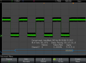
To find out if there is some kind of rare glitch we use the mask test function of the scope:
I’ll call that a promising result. When cranking up the bit rate to 250 kbit/s we get the same good result. So we may assume that at least an unidirectional serial communication is possible…
